
 Ita
Ita Deu
Deu
If you flicked straight to this article after seeing the title, it means that you have experienced this situation in the past, or that you are probably going through it now and you have yet to find an effective solution.
We all know how complex the tool vibration topic can be.
So much so that when vibrations start to become “the problem” of the day, the stress level quickly rises. This problem is experienced in a very negative way, since many times we feel helpless when faced with this problem, we do not have control over the situation and this makes us nervous, often driving us to make the wrong choices in an attempt to solve the situation.
In addition to this, I am not telling you anything new by saying that producing components when vibrations are present has many negative aspects and no positive ones.
Below is a list of the more common ones:
- PIECE SCRAPPED FOR NON_CONFORMANCE
- SHORTER TOOL SERVICE LIFE
- BREAKING OF THE TOOL
- PREMATURE WEAR OF THE MACHINE BEARINGS
- INCREASE IN MACHINE DOWNTIME
- PRODUCTION LOSS
- SLOWING DOWN OF CUTTING PARAMETERS AS A TEMPORARY SOLUTION
- PERSONAL FRUSTRATION DUE TO LACK OF CONTROL OVER THE SITUATION
In addition to these negative aspects, tool vibration causes stress in the relationships of staff involved in trying to resolve this problem.
Usually, the quality department reports the problem to the production department, which of course stops all production.
At this point, a series of endless inspections begin aimed at solving the problem as quickly as possible.
Why does it have to be done so quickly? Because, as we all know, logistics needs for the delivery date promised to the customer to be met, and this creates more stress.
To cap it all off, the sales department comes along and blesses everyone with the usual phrase:
WE BRING YOU THE CUSTOMERS AND YOU LET THEM GET AWAY!
All the above occurs and, if we are lucky, the problem is pinpointed right away within the company.
Otherwise, if it is the customer to discover the problem, it’s like a bomb going off, and stress levels at the company hit the ceiling.
At this level, in addition to having spent more money, because perhaps the component has already been assembled, packed and shipped, the company’s reputation is also jeopardised.
As you’ll know, it takes a lifetime to win over a customer, and with the tiniest vibration he can be lost! (Just to keep to the point).
So, this is the reason why the bomb effect takes on a NUCLEAR type of power!
SO, WHAT DO YOU DO WHEN YOUR TOOL STARTS TO VIBRATE?
The traditional route that I have seen companies take many times is the following:
- MAKE ALL THE SCRAP DISAPPEAR AS FAST AS POSSIBLE
- YOU TRY TO INVESTIGATE, UNSUCCESSFULLY, IF AN OPERATOR HAS CHANGED SOMETHING
- YOU REDUCE THE SPINDLE ROTATION SPEED, WHICH WORKS ALMOST ALL THE TIME. ON THE DOWNSIDE, THIS SOLUTION SLOWS DOWN THE OPERATION
- YOU CONTACT THE TOOL MANUFACTURER TO TRY TO FIND THE SOLUTION TO THE PROBLEM
- YOU CONTACT OTHER SUPPLIERS IN THE HOPE THAT THEY HAVE EXPERIENCED THE SAME PROBLEM AND HAVE MANAGED TO SOLVE IT…
- YOU START TO CONDUCT TESTS GUIDED BY YOUR INSTINCT, CHANGING MORE THAN ONE VARIABLE AT A TIME JUST TO GET MORE AND MORE CONFUSED
I think we have all been through these situations.
Years ago, while watching in-house tests, I saw the same situations, more or less, repeat themselves.
Until the time came when, tired of EXPENDING SO MUCH ENERGY in this area, we set up a team of professionals who basically grabbed the bull by its horns.
After having dedicated time to these issues, we learned that vibration is a precise science and not as mysterious as we thought.
Today, we will take an interesting journey to show you the sources of vibrations that can be generated in a machine tool.
During this journey, I will be sharing some interesting concepts which I had the chance to learn.
If you are in any way involved in the world of machining processes, these concepts will certainly help you to improve your production considerably.
IT ALL STARTS WITH A SIMPLE VIBRATION…
Having seen how a vibration can put a department in a difficult position or even jeopardise a company’s reputation, let’s examine in detail what’s behind it…
A vibrated component is only the final result of a series of situations that are not under control. Below please find a list of the 13 basic points (some of them are obvious, others are not) that directly influence vibration and that you perhaps have never thought of checking:
- WORN TOOL
- TOOL NOT PROPERLY HELD IN THE TOOL HOLDER
- WORN TOOL HOLDER CONE
- WORN TOOL HOLDER RETENTION KNOB
- WORN MACHINE SPINDLE TAPER
- WORN MACHINE SPINDLE BEARINGS
- WORN LINEAR BEARINGS OF THE 3-AXIS MODULE
- TOOL CONE CLAMPING STRENGTH
- UNSTABLE PIECE CLAMPING
- WRONG TYPE OR LACK OF COOLANT
- TOOL HOLDER and/or TOOL NOT BALANCED
- SPINDLE NOT BALANCED
- MACHINE STRUCTURE RESONANCE
Let’s take a quick look at these points, starting with the first, “WORN TOOL”.
This is the one that is always inspected and blamed first, so I would just skip right to the second one “TOOL NOT PROPERLY HELD IN THE TOOL HOLDER”.
Although this point may seem obvious, it actually isn’t: an improperly tightened tool can be the cause of the vibration.
Usually, when held with an elastic collet, a significant improvement can be observed by switching to hydraulic clamping, since the latter is stiffer thanks to the hydraulic strength of the closing mechanism.
In the more difficult cases, I also experimented with heat or shrink clamping.
This system completely eliminates any play, making the tool holder and the tool a single piece which greatly benefits rigidity.
The issue of the “WORN TOOL HOLDER CONE” is often forgotten.
It is taken for granted that the cone never wears out, that it lasts forever, which is the reason why many people fail to think that it might be in fact the cause of the problem.
The solution is to simply replace the cone.
Along with a worn out tool holder, there is also the issue of the “WORN TOOL HOLDER RETENTION KNOB” which, for the same reasons as the cone, is also thought to be everlasting, when if fact its tight contact points are subject to wear. “WORN MACHINE SPINDLE TAPER”: this happens when the machine has been producing for years and there have been millions and millions of tool change cycles.
In this case, the manufacturer can replace the spindle or, in certain cases, grind the taper to restore it.
One point which, on the other hand, is often taken into account, even though it is not always the cause, is the “WORN MACHINE SPINDLE BEARINGS”, since it is a quite logical cause.
The seventh item is “WORN MODULE LINEAR BEARINGS”: statistics indicate this cause to be rare; in case of replacement, the problem is more associated with programming errors resulting in system crashes.
One point which is rarely checked is the “TOOL CONE CLAMPING FORCE”: this item checks cone tightening ISO40 to a calibration of about 1,000 kg.
If the customer fails to carry out preventive maintenance, this item can often become a problem and generate vibrations on the piece, up to the loss of the holder during tool change.
“UNSTABLE PIECE CLAMPING”: when we speak of vibrations, we immediately focus on the tool; however, sometimes the solution involves exactly the opposite side, in the clamping of the piece due to unstable clamping points, or drops in hydraulic pressure.
A few months ago, I had the following problem caused “WRONG TYPE OR LACK OF COOLANT”: it might seem a bit ridiculous, but for four days the customer went crazy trying to get back the quality of finish he was used to.
The reason for this was that an operator had replaced the tool holder with one that did not allow the coolant to flow though.
So, without the coolant, the same tool was unable to work as before.
The result: four days spent blaming someone else, including the replacement of bearings followed by a request for our assistance.
During our service call, thanks to a simple check list the PORTA Solutions technician was able to find the holder that was not letting the coolant flow through.
“UNBALANCED TOOL and/or TOOL HOLDER”: many people think that balancing is required only with tools running over 20,000 RPM. This is wrong, since tools from 4,000 to 6,000 turns are also affected by imbalance.
For this topic, there is a well-defined standard that helps us understand what the parameters are. It is standard DIN 69888, which specifies that the bearing load caused by unbalance must not exceed 1% of the bearing’s dynamic load capacity
Few people know that when ordering tools, reference can be made to this standard so that the supplier is required to deliver balanced tools.
Still on the topic of balance, here is the other item: “SPINDLE NOT BALANCED”.
It is very important to balance the spindles; in fact, this operation is carried out as standard procedure in the following manner.
The vibration and balancing measurements are taken by using an instrument called balancer, which is divided into two phases: a measurement phase and a balancing phase.
MEASUREMENT: carried out in compliance with standard ISO 10816 “Evaluation of machine vibration by measurements on non-rotating parts”.
BALANCING: carried out in compliance with ISO 1940 “Balancing of rigid rotors”. According to standard ISO 10816-3, spindles can be classified in Group 2, which entails a vibration level classifiable as:
- GOOD: machine in perfect condition up to 1.4 mm/s RMS.
- ACCEPTABLE: machine suitable for long-term use with no need for any operation from 1.4 to 2.8 mm/s RMS.
- TOLERABLE: machine not suitable for long-term operation, consequently requiring service as soon as possible from 2.8 to 4.5 mm/s RMS.
- UNACCEPTABLE: machine not suitable for operation above 4.5 mm/s RMS.
I will conclude by saying that, in the case of PORTA Solutions, we declare that the aforementioned operations are carried out in compliance with the following standards:
- ISO 10816
- ISO 1940
In addition, we go even further because, as of January 2015, WE HAVE BEEN COMPLYING WITH THE MAXIMUM CALIBRATION LIMIT OF 1.0 mm/s RMS (40% LESS COMPARED TO THE VALUE SET FORTH IN THE STANDARD), and I can assure you that this has reflected positively on the following aspects:
- IMPROVED CUSTOMER PART FINISH
- LONGER TOOL SERVICE LIFE
- LONGER SERVICE LIFE OF THE BEARINGS
- LONGER SERVICE LIFE OF THE MACHINE TOOL
- FASTER CYCLE TIMES
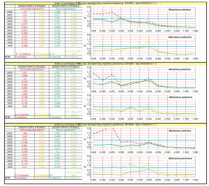
The Table below is provided as an example of the Spindle Balancing of our MULTICENTER under the threshold of 1.0 mm/s RMS (40% LESS COMPARED TO THE STANDARD!):
In thirteenth place, at the bottom of the list of the 13 items that directly affect vibrations, we find a crucial topic, practically the most important one, the one that makes the difference.
Then why is it at the bottom of the list?
Because this point is “MACHINE STRUCTURE RESONANCE”. Clearly, if you already own a machine tool, there is not much you can do; on the contrary, if you are only in the selection phase, I can prove to you that:
THE MULTICENTER WAS DEVELOPED IN COLLABORATION WITH THE UNIVERSITY OF BRESCIA IN ORDER TO REDUCE VIBRATIONS AS MUCH AS POSSIBLE!
Lastly, I give you the chance to answer two questions, in order to better evaluate the situation you are currently experiencing:
WHAT WOULD CHANGE IN YOUR COMPANY IF YOU ELIMINATED VIBRATION-RELATED PROBLEMS FOR GOOD?
… AND WHAT HAPPENS IF YOU KEEP ON FIGHTING VIBRATIONS BY ADOPTING TEMPORARY SOLUTIONS?
Maurizio Porta
Expert in Flexible Production